


Bambu Lab A2L Combo Unboxing Review!
3DMart is an authorized Bambu Lab dealer. Reservations for A2L demonstrations are accepted at our store!

Included Items List

Part 1: Unboxing Guide
Removing Packaging and Taking Out Accessories
Step 1: Removing the Packaging
-
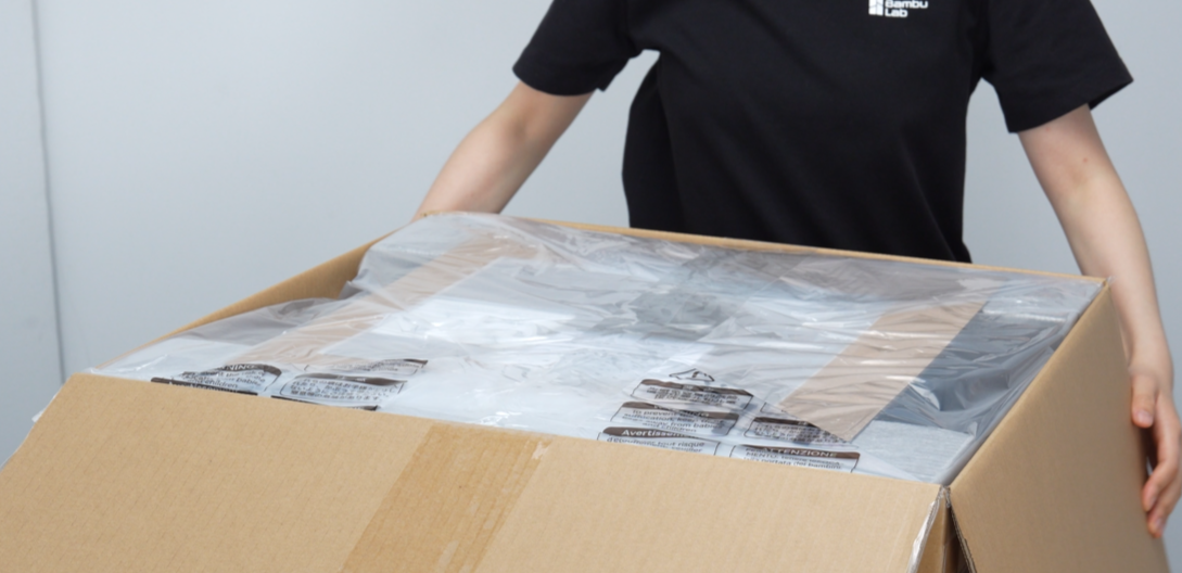
Open the outer box with a cutter, tear the moisture-proof bag, and place it over the outer box.
-
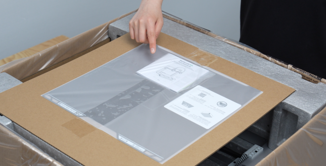
Read the quick start guide carefully to review unboxing precautions in advance.
Step 2: Taking Out Accessories
-
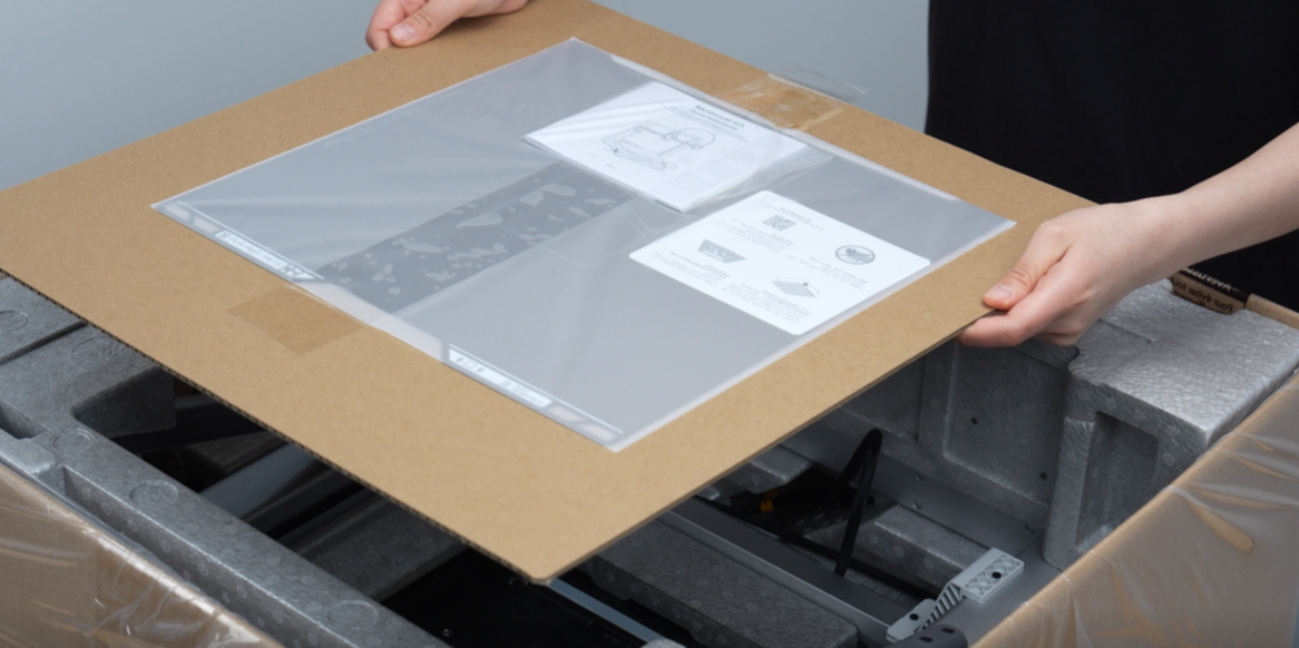
Remove the build plate.
-
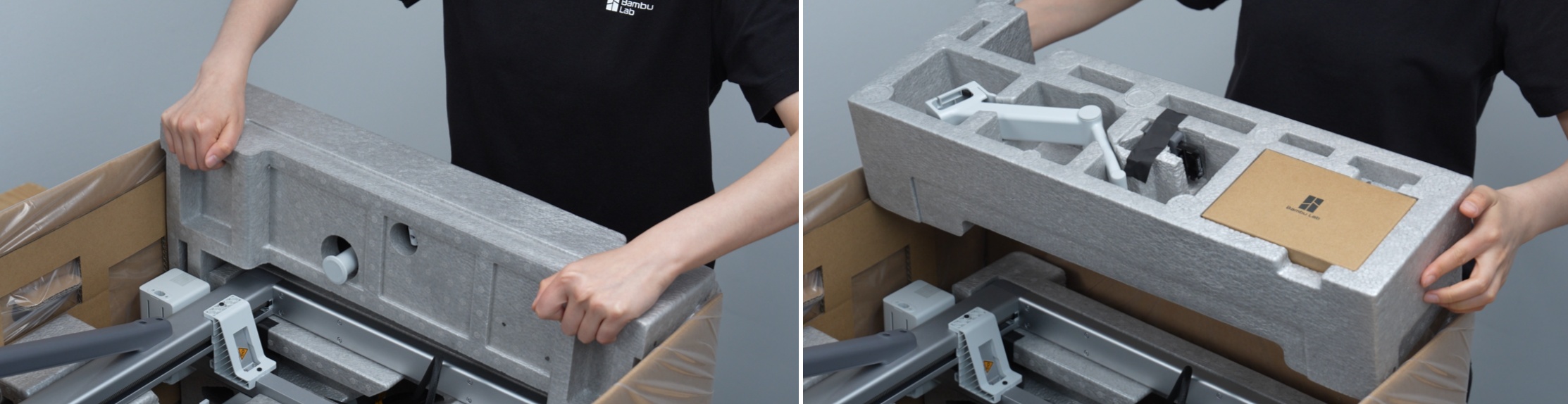
Remove the upper cushioning material (foam) and the parts inside it (accessory box, purge wiper, spool holder).
-
Remove the other upper cushioning material.
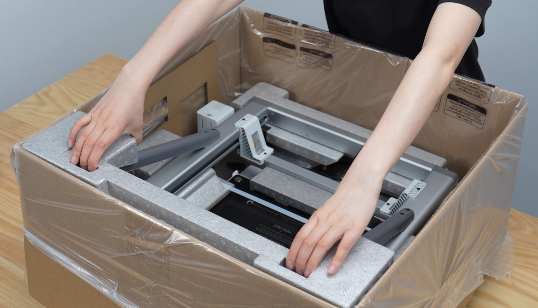
-
Take out the toolhead cable, hold the dark gray part, lift the printer gantry, and place it vertically on a stable, flat surface.
⚠️ Caution:
Do not hold the X-axis of the gantry. Carry it by holding the Z-axis on both sides, or the dark gray structural part on the back of the Z-axis.

-
Remove the protective cardboard, and while being careful not to pull on the cable ties, lift both sides to remove the printer base. Place the base on a stable, flat surface.
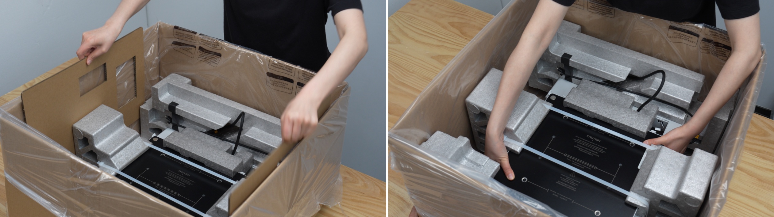
-
Remove the PTFE tube and sample filament.
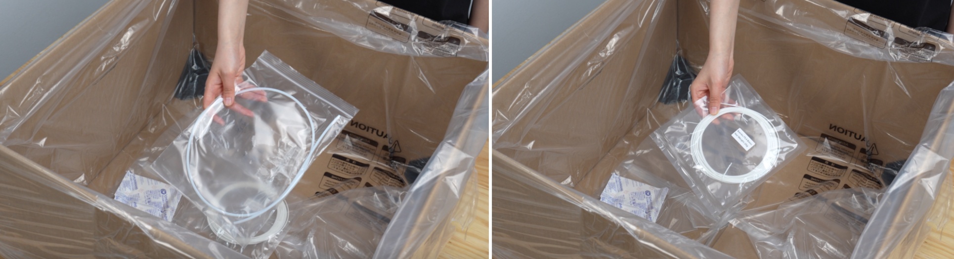
Step 3: Removing Base Packaging
-
Remove the power cord stored in the base cushioning material.
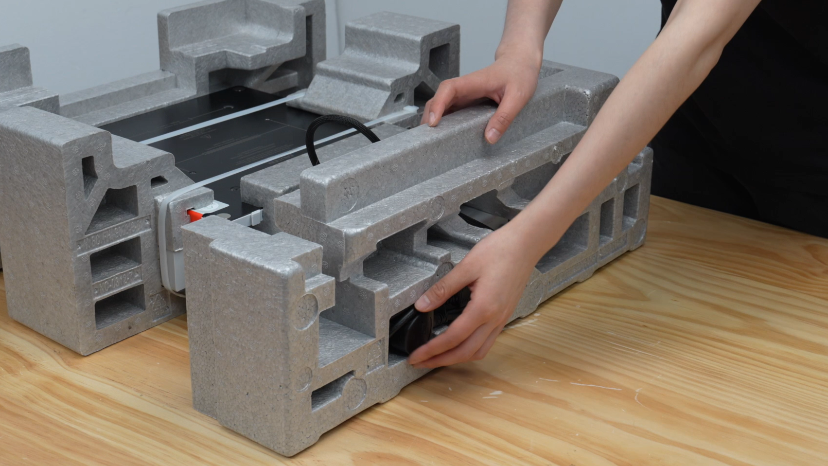
-
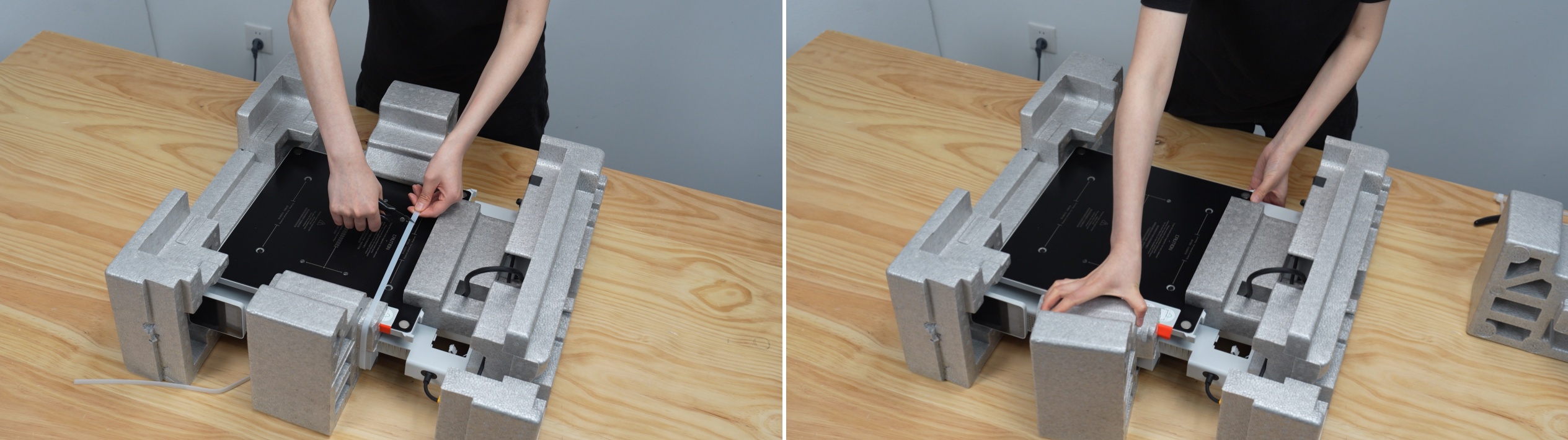
Cut the cable ties and remove the cushioning material from the left and right sides of the base.
-
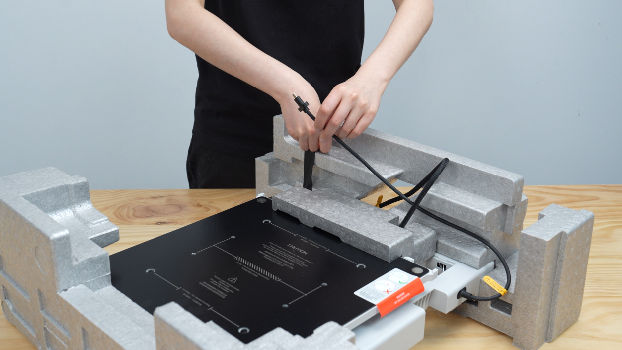
Peel off the tape and remove the integration cable (main cable bundle).
-
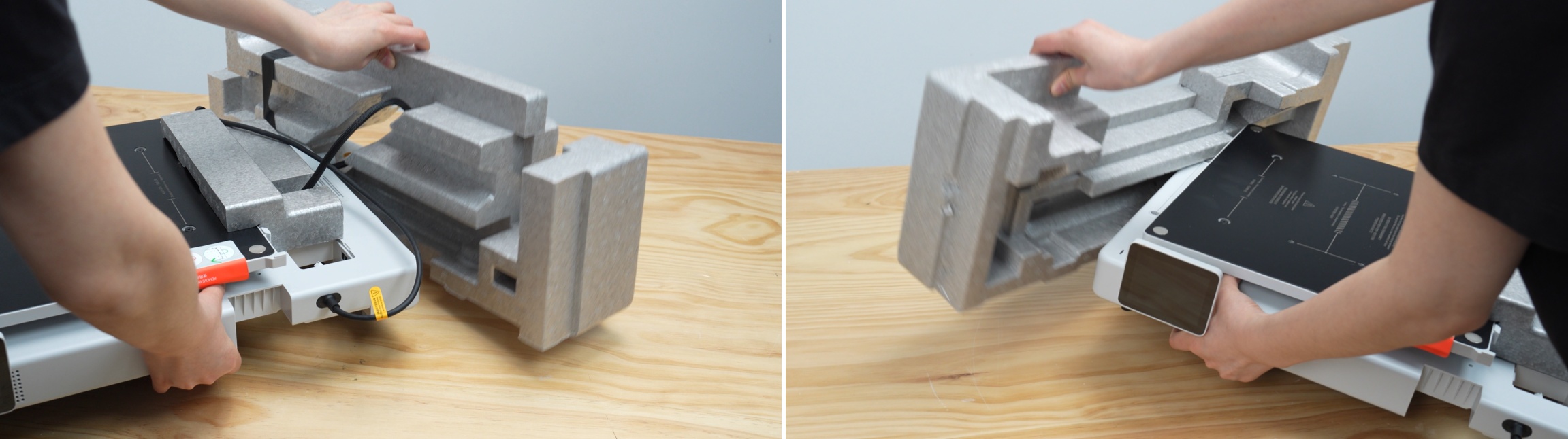
While supporting the base with your hand, remove the cushioning material from the front and back of the base.
-
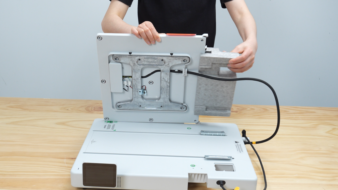
While supporting the heatbed with your hand, remove the cushioning material from the back of the heatbed.
Part 2: Bambu Lab A2L Assembly Guide
Step 4: Securing the Heatbed
-
Read the warning label carefully, ensure the heatbed cable is not twisted, and then peel off the label from the heatbed.

-
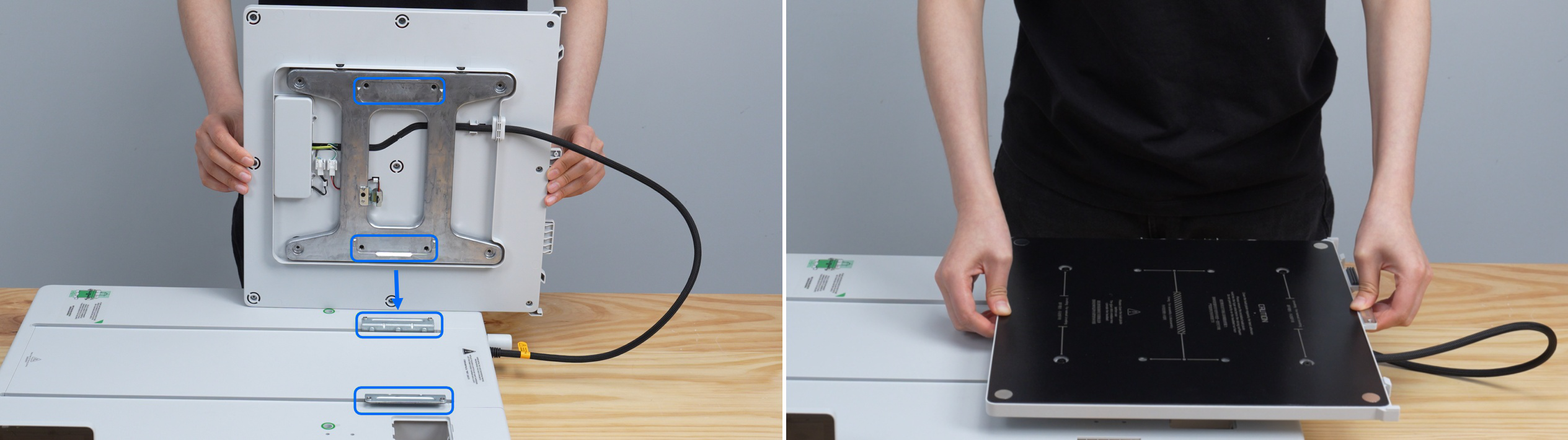
Align the screw holes of the heatbed and the Y-axis carriage, and place it neatly in one go.
-
Take out the heatbed mounting screws from the accessory box, tighten them in the specified four locations, and secure the heatbed. Ensure that the heatbed and Y-axis carriage are firmly locked.


Step 5: Assembling the Base and Gantry
-
To prevent the cable from being pinched during assembly, pull the Z-axis motor cable upwards and hold the integration cable with your hand.
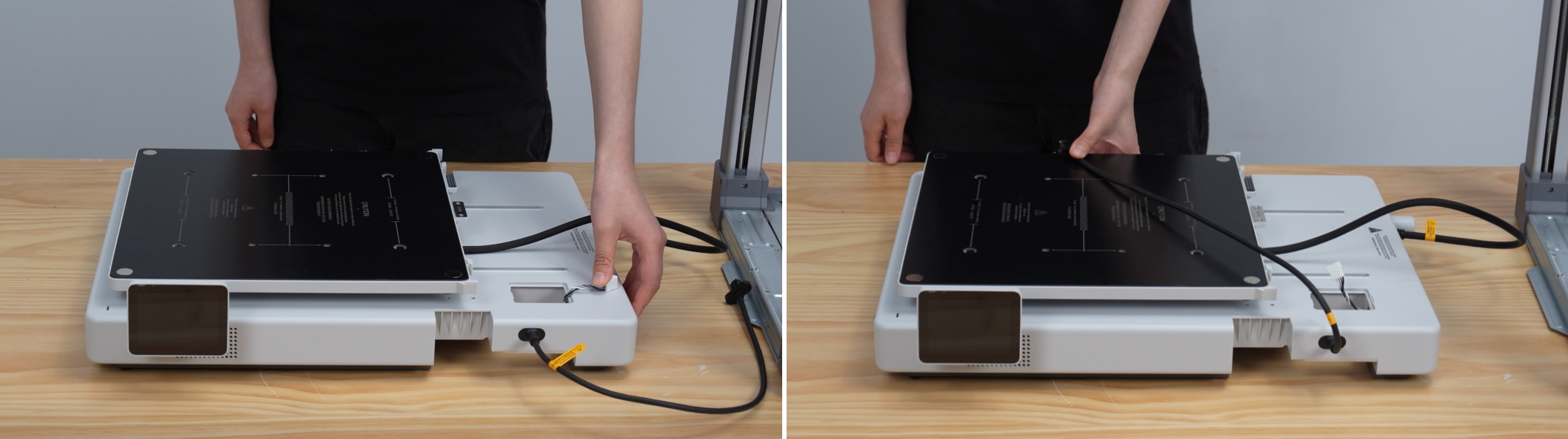
-
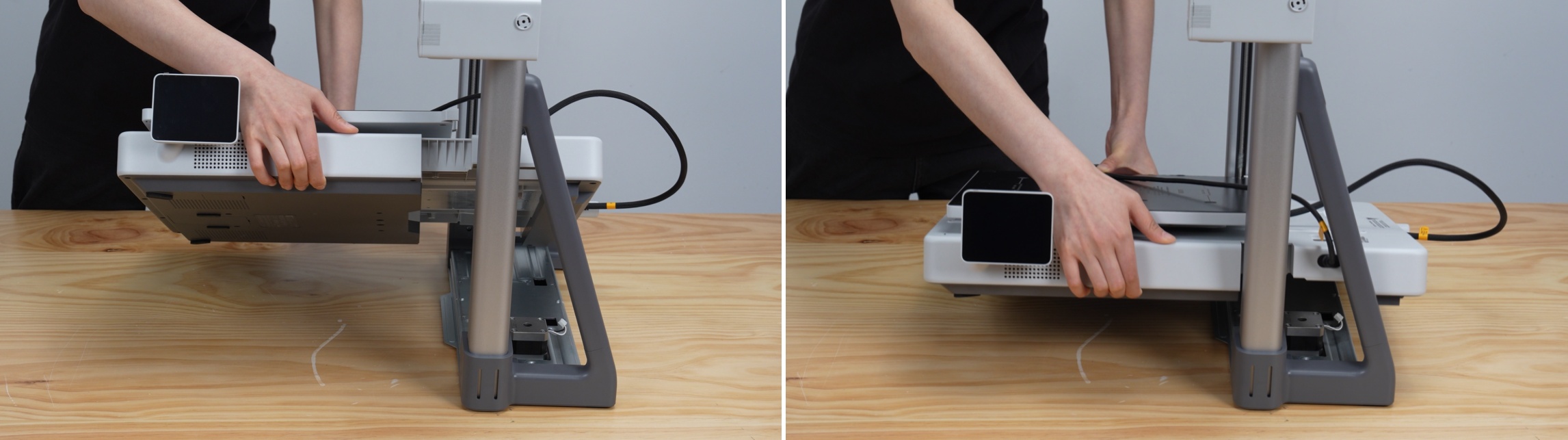
As shown in the diagram, tilt the base at approximately 45 degrees and pass the gantry through. Align the joint between the integration cable and the base with the triangular gap in the gantry, positioning it correctly to avoid hitting other parts.
-
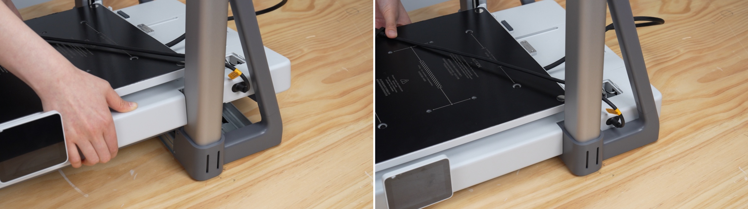
Once the notch in the base is aligned with the gantry, slowly lower the base to make it completely flush with the gantry.
-
Route the integration cable through the triangular gap in the gantry and position it appropriately to the side.
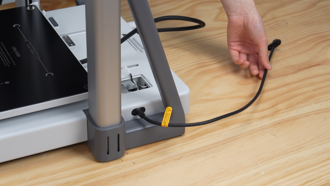
Step 6: Removing the Y-axis Top Cover
-
Push the heatbed all the way to the front (front end).
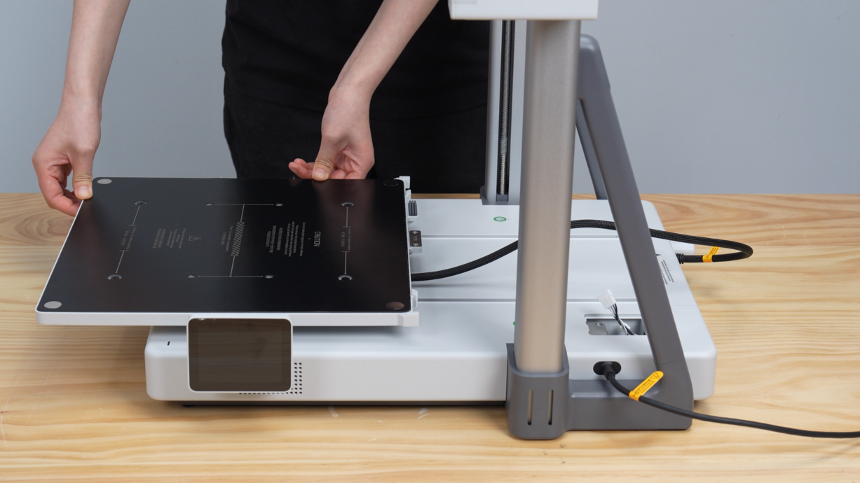
-
Lift the rear end of the Y-axis top cover and gently remove the cover.
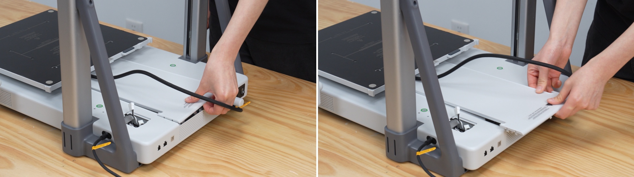
Step 7: Securing the Base
-
Take out 10 base fixing screws from the accessory box and use an H2.0 wrench to install them in the holes marked in green.



🚨 Important Screw Check:
The base fixing screws must be fully tightened. Loose screws can prevent smooth movement during operation, cause interference with the Y-axis, and lead to skipped steps or abnormal operation. If you experience operational errors during printing, first return to this step and check the screws.
Step 8: Lubricating the Y-axis Guide Rail
-
Take out the lubricant from the accessory box.
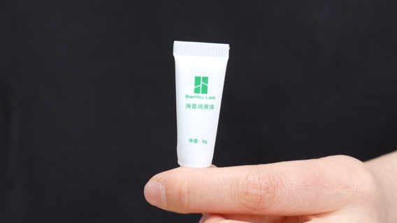
⚠️ Caution:
Always use liquid "lubricating oil" for maintenance. Never use solid or paste-like "grease," as it may damage the drive mechanism.
-
Apply a small amount of lubricant to the upper end of the Y-axis guide rail (on the steel shaft).
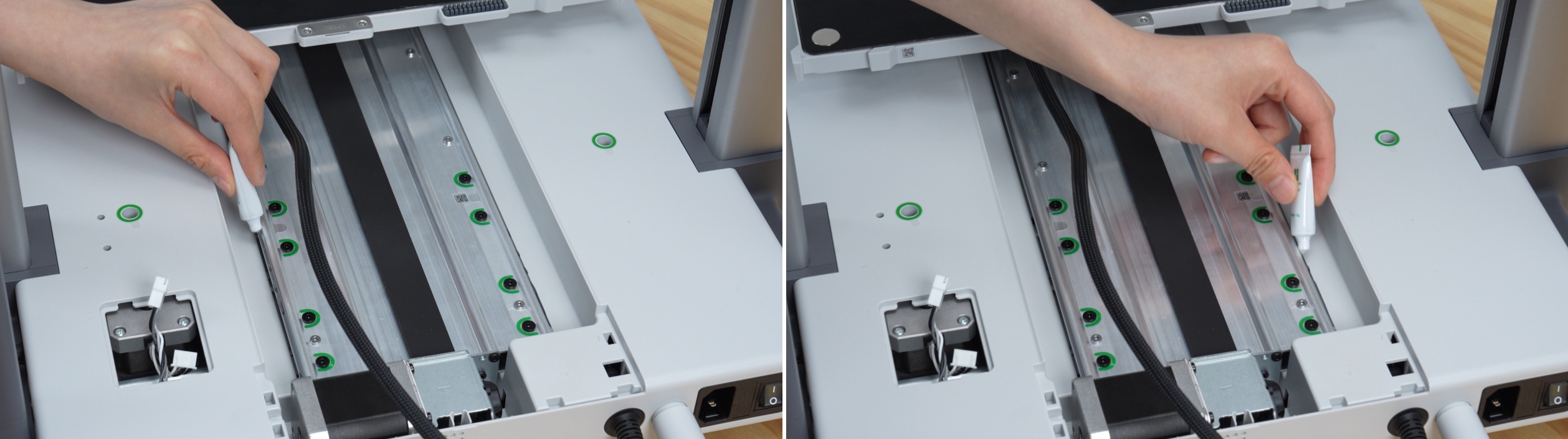
-
Using the tip of the lubricant tube, evenly spread the lubricant over the curved surface of the guide rail (on the steel shaft).
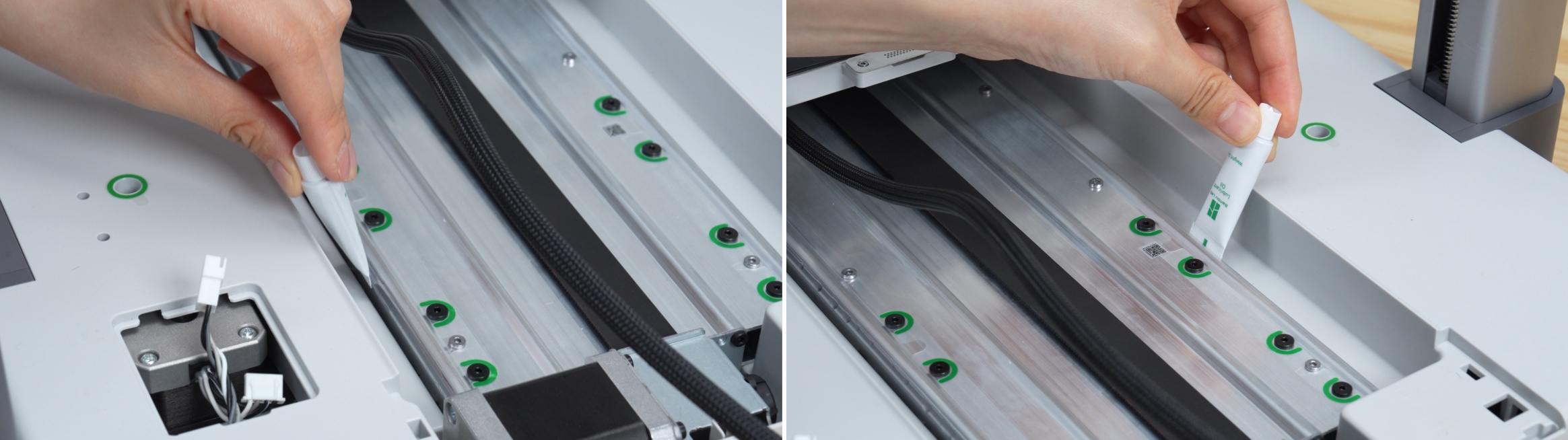
-
Push the heatbed all the way back (rear end).

-
Lubricate the front steel shaft of the printer.
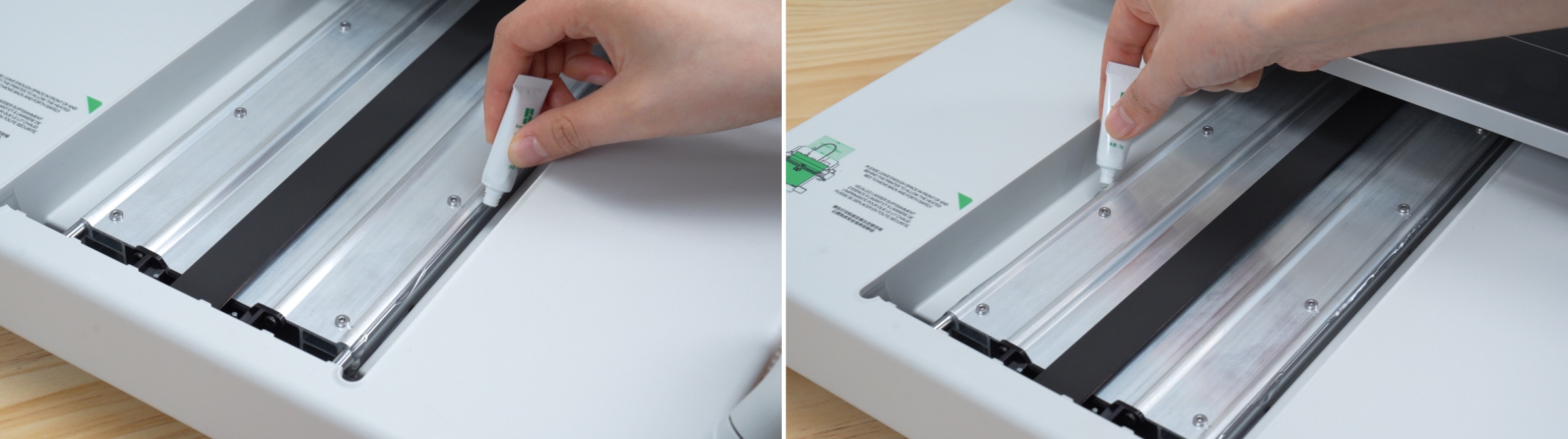
-
Using the tip of the lubricant tube, evenly spread the lubricant over the curved surface of the guide rail (on the steel shaft).
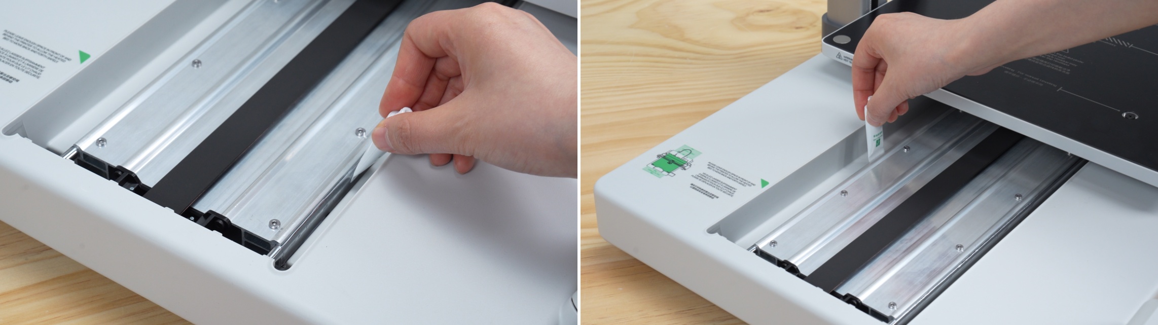
-
Move the heatbed back and forth to evenly distribute the lubricant.
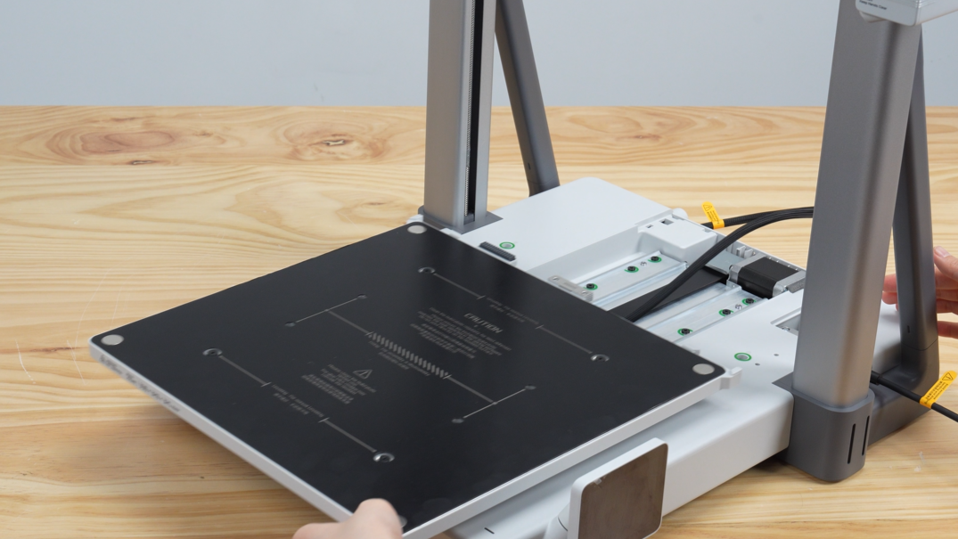
Step 9: Installing the Y-axis Top Cover
-
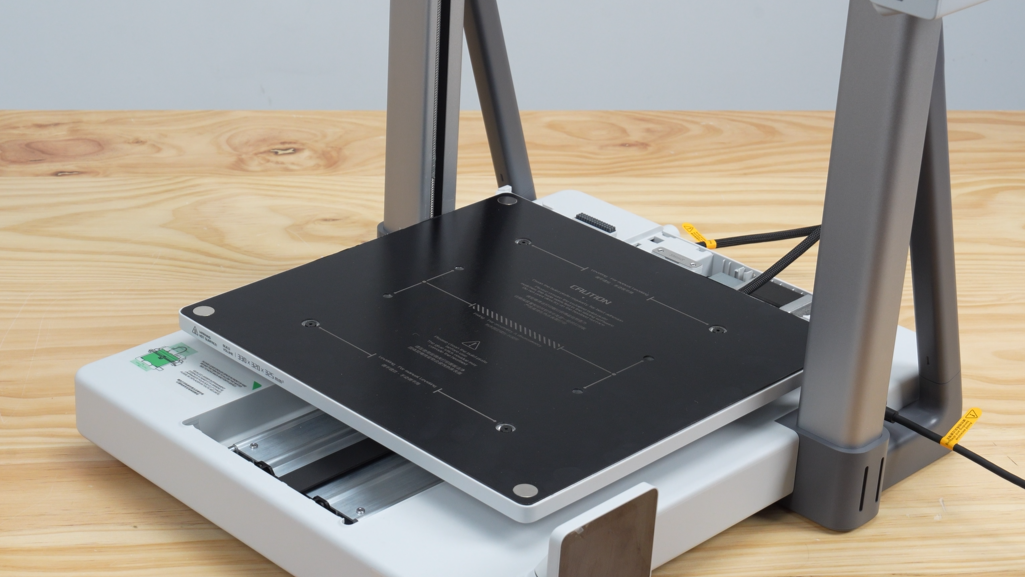
Move the heatbed to the approximate center.
-
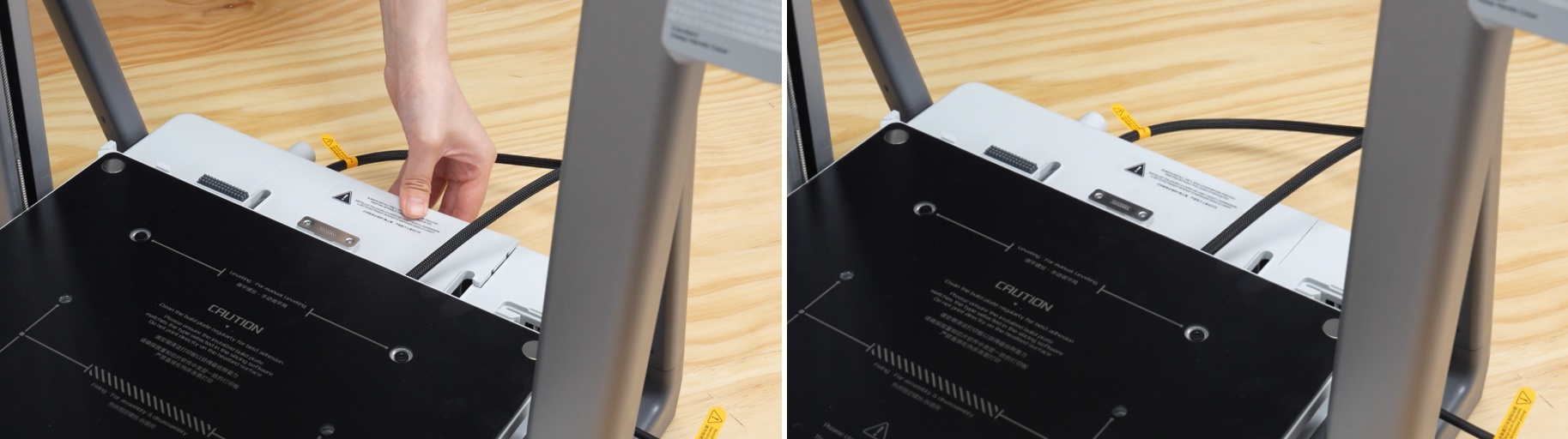
Align the front tabs of the Y-axis top cover with the mounting slots and gently slide the cover back into its original position.

-
Push down on the rear end of the Y-axis top cover and ensure the tabs are fully locked.
Step 10: Connecting the Z-axis Motor Cable
-
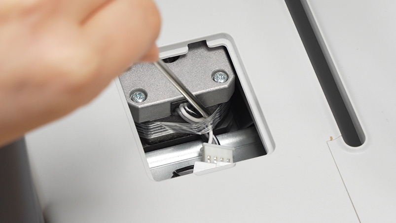
Push the heatbed towards the screen, use an hex wrench to peel off the cable fixing tape, and manually remove the tape from the Z-axis motor.
-
Connect the Z-axis motor cable.
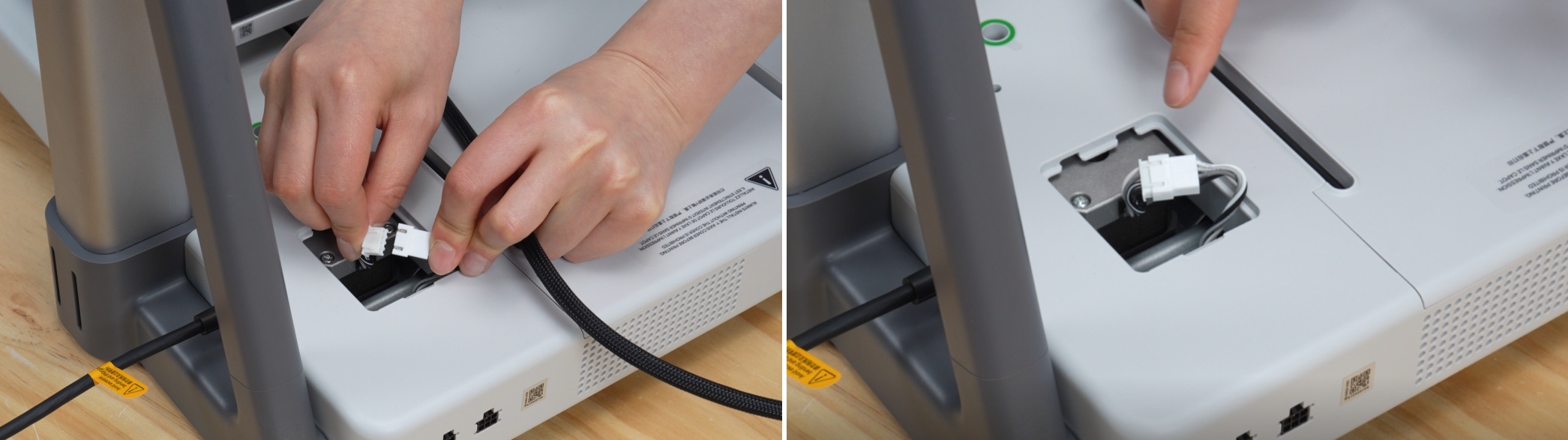
-
Return the cable to its original position to ensure it does not obstruct the mounting area.

-
Take out the Z-axis motor cover from the accessory box and cover it in the correct orientation.

Step 11: Connecting the Integration Cable
-
Straighten the integration cable and ensure there are no twists.
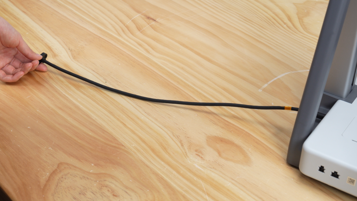
-
Ensure the connector is correctly oriented (the letter "A" facing upwards) and insert the integration cable into the back of the X-axis motor box.

-
Tighten the two integration cable fixing screws to secure the cable.

Step 12: Removing the Z-axis Lock
-
Loosen the four screws with an H2.0 wrench.
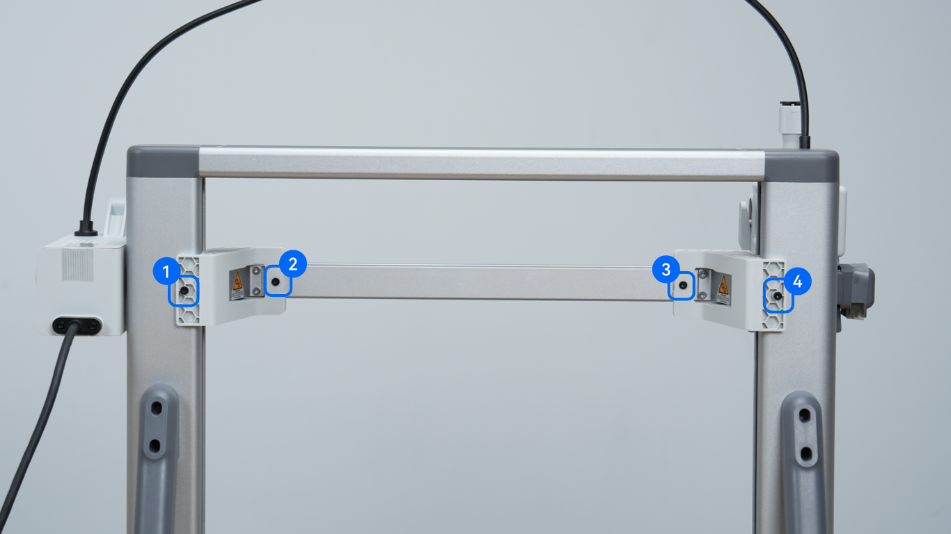
-
Remove the two Z-axis locks.

Step 13: Installing the Purge Wiper Assembly
-
Manually move the toolhead to the center of the linear rail.

⚠️ Important Assembly Order:
Before installing the purge wiper, always manually push the toolhead to the center of the crossbar. Failure to do so will cause the purge wiper structure to lock the toolhead, leading to hardware collision, abnormal noises, or system errors during startup operation.
-
Take out the purge wiper from the accessories and open the back cover.
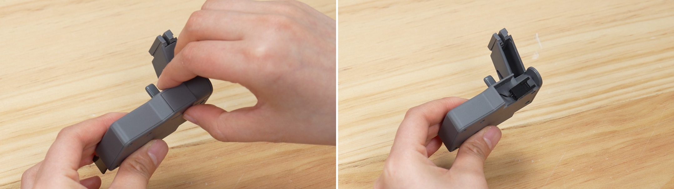
-
Hold the cable at the end of the X-axis by hand to prevent the slot from being blocked, then slide the purge wiper into the slot.
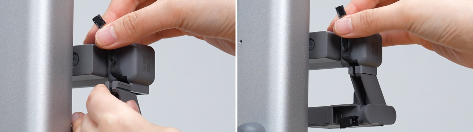
-
Take one purge wiper screw from the accessory box and tighten it with an H2.0 wrench to fix the purge wiper.

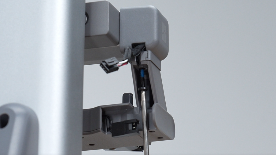
-
Insert the connection cable into the cable connector.
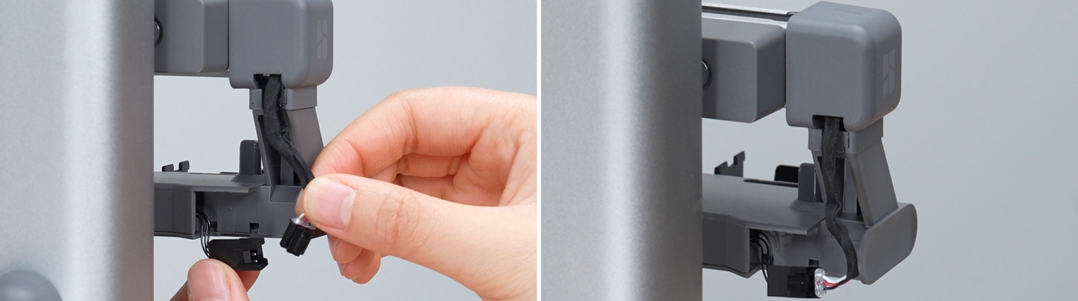
Do not forcefully pull the very thin connection cable inside the purge wiper, as this may cause a disconnection. When wiring, it will be smoother if you pull the cable net at the end of the X-axis forward slightly before connecting.
-
Organize the cable and fit it into the cable slot, positioning the cable connector to the left.
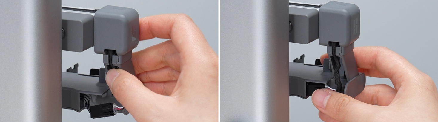
-
After confirming that the cable is arranged as shown in the diagram, attach the back cover of the purge wiper.

Step 14: Unfolding the Touchscreen
-
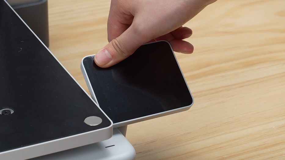
Unfold (raise) and secure the touchscreen.
Step 15: Installing the Build Plate
-
Hold the build plate with both hands, align its edges with the heatbed, then gently lower it to let the magnets adhere.

Step 16: Removing Protective Film and Tape
-
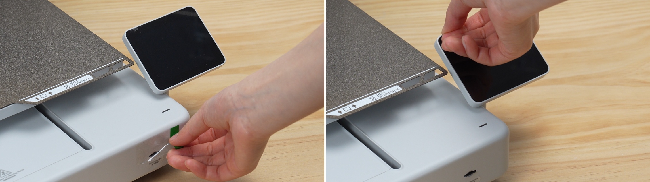
Peel off the protective film from the screen and near the SD card slot.
-
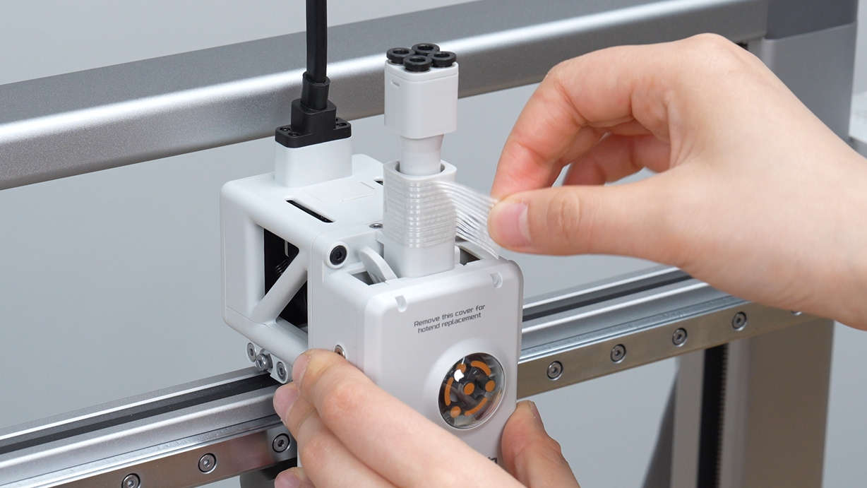
Peel off the fixing tape applied to the toolhead.
-
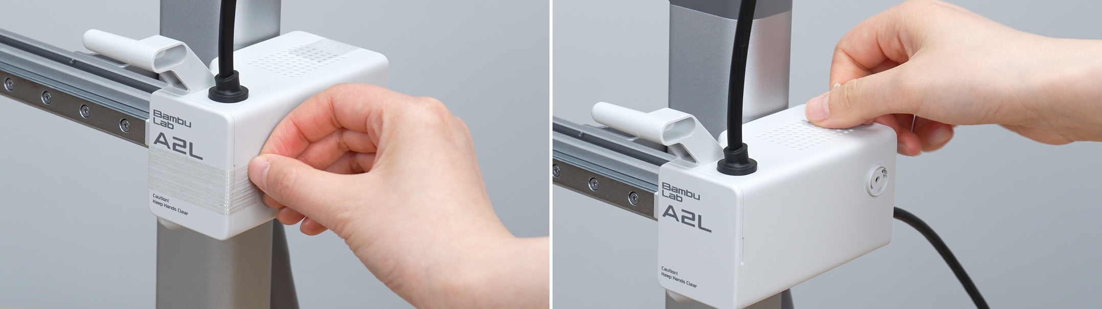
Peel off the tape applied to the front and back of the X-axis motor box.
-
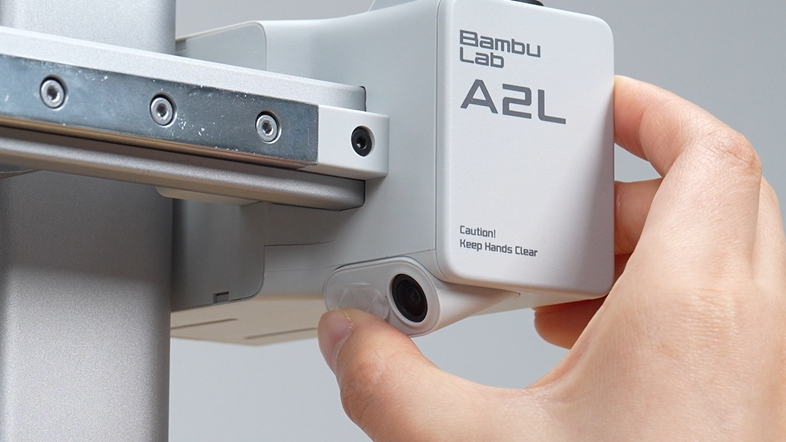
Slide open the camera's privacy cover.
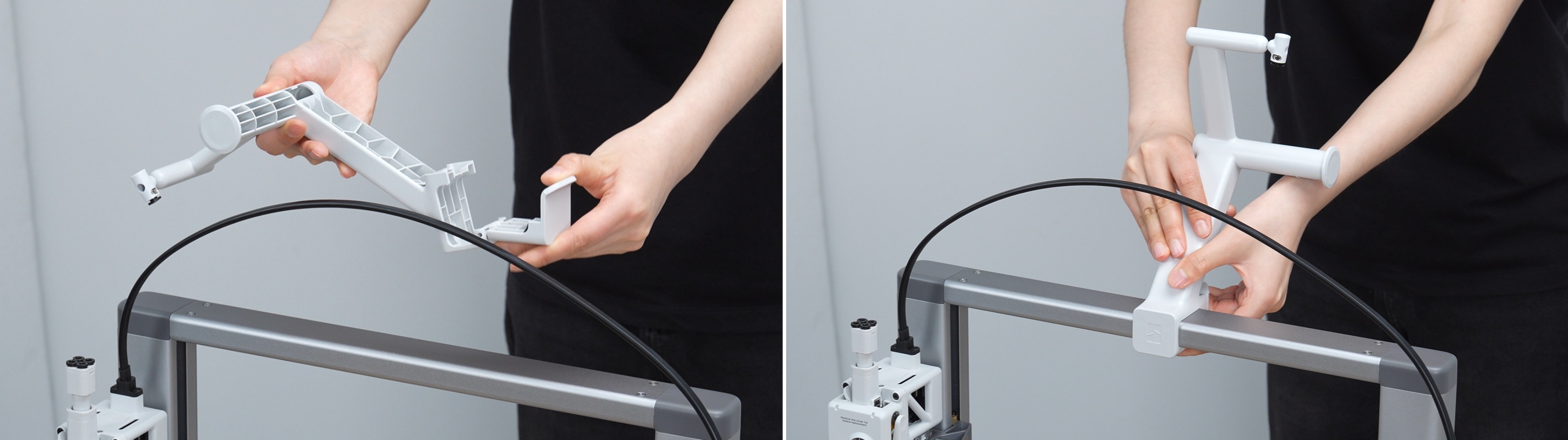
Step 17: Installing the External Spool Holder
-
Take out the external spool holder and fix it to the frame.
-
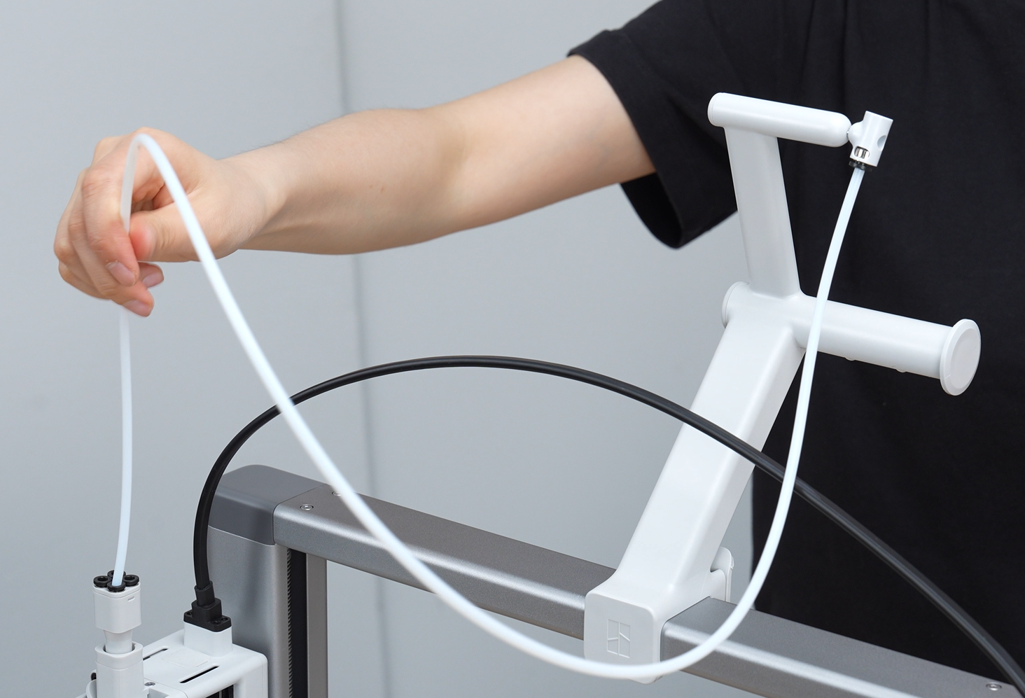
Take out the PTFE tube, connect one end to the tube connector of the holder, and the other end to any filament feeding port on the toolhead.
Part 3: Powering On and Initial Calibration, and AMS lite Multi-Color System Assembly
Step 18: Powering On the Printer
-
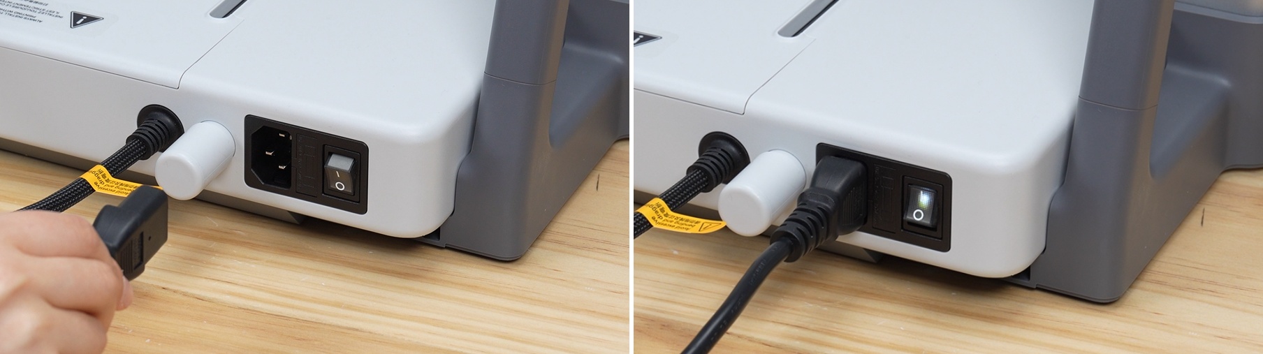
Plug in the power cord and turn on the main power switch.
Step 19: Installing the Multi-Color Automatic Filament System (AMS lite)
- Assemble the four rotary filament holder parts of the AMS lite according to the color codes.
- Also, use the included special screws to securely connect the bottom structure of the AMS lite to the dedicated stand.


-
Connect the four PTFE tubes sequentially to the four main filament feeding ports of the AMS lite, following the logic of "short tubes in front, long tubes in back."


Finally, connect the other end of the four tubes to the 4-hole hub connection port on top of the printhead, and the multi-color automatic printing system assembly is complete.

Step 20: Complete the initial full automatic calibration according to the on-screen instructions
-
Reconfirm that the build plate is properly adsorbed to the heated bed. Once the printer is powered on, follow the on-screen UI guide to complete resonance compensation (vibration correction), auto bed leveling, and system initial operation initialization.
Tip: If you skipped network connection or Bambu Handy mobile app binding during unboxing, you can always reconfigure Wi-Fi settings and bind the device from the settings page after the equipment has completed its full calibration.

💡 Who is the Bambu Lab A2L suitable for:
- 3D Printer Beginners and Entry-Level Users: The A2L is an upsized and upgraded successor to the best-selling "A1". As an entry-level device with overwhelming friendliness, out-of-the-box printability, and comprehensive error prevention features, its price and cost-effectiveness are overwhelmingly competitive. If you don't want to worry about fine-tuning hardware parameters, this is the optimal choice.
- Farm Owners with High-Efficiency Multiple Unit Operations: If you have a need for large model output or small to medium-scale mass production requiring extremely high stability, and your printing materials do not require special engineering plastics, the "A2L Combo," with its easy operation and very high level of automation, will be a powerful tool for building a high-productivity 3D printer farm.